
To begin, I'd like to that MatX for putting together a guide on the MAC Forums and Sneeper1980 for helping to answer some questions.
Before you even get started, you need to get the right equipment for the job. Below is the list of tools you will need and a few that are optional which can make your experience run a little smoother.
Required:
Batteries - To light up the LEDs, you need a power source. This is where batteries come in. They come in many shapes and sizes, with a variety of characteristics. Wikipedia has a very nice guide for this. The image below is of a 10 pack of LR41 batteries. These are the same batteries that are used to power the LED unit that comes with the MG 00 Raiser. These batteries have 1.5V. I also have some larger 3V batteries and some smaller 1.55V batteries. Any battery (or batteries) will work, but the size and space you have to work with and the amount of money you wish to spend, will determine which batteries you need for your project.

Resistors - What they do is a bit technical and not really necessary. Just understand that you should use them or you risk damaging the components in your circuit. Below is an image of the varity pack of resistors I picked up. For the basic circuit designs, you wont need anything bigger that 300 or 400 ohms. Each resistor has a color code on it. They are a bit tricky. First thing to do is make sure the tolerance band (usually gold) is on the right. The first two colors indicate specific digits. The next color is the multiplier. The last color is the tolerance color. For an example and the number associated with the colors, check out Wikipedia's guide. From personal experience, depending the manufacturer, the red and orange band may look very similar.

Solder - Solder is a fusible metal alloy which is used to connect metal pieces.

Soldering Iron - This tool is used to heat and melt the solder. Once melted, it can be applied to metal parts. Once the soldering iron is removed from the solder, it will cool and harden. This will cause the two parts to be joined together. More on how to do this in the future.

Wire Cutters - Most modelers are familiar with this guy. These will be used to cut and trim excess wire.

Wire - Give the last item, this is pretty obvious. Wire comes in various sizes, know as gauge (aka AWG). The larger the number, the thinner the wire. Below is 22 gauge wire.
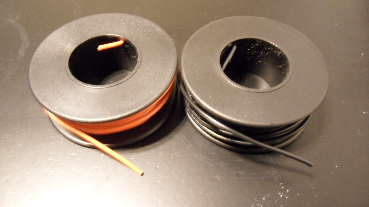
22 gauge wire is sufficient for many MG or larger sized kits and is fairly easy to find. However, 26 gauge maybe a better choice if you are working in tight spaces. Below is a comparison between 22 and 26 gauge wire.

LEDs - Obviously, you will also need LEDs. They come in lots of shapes and sizes. But more importantly are their characteristics. I will get into all of this in Part 2.

Optional:
Soldering Iron Stand - Personally I like having one of these. I can be a little clumsy at times and it's nice to have a protective stand for the iron while it's plugged in. Although I haven't burnt myself (at least not yet), I have knocked it off the little rocker it comes with and had it burn the table. In addition the sponge is nice for wiping of excess solder.

Wire Stripper - Wire strippers are used to remove the protective casing around the wire. If you do purchase a wire stripper, be sure to get a good pair. A cheap pair will not be as sharp or can dull quickly and cause a lot of headaches. Personally, I do not have any wire strippers. Back in college I got in the habit of using wire cutters to cut through the casing. But I must warn you, until you get the hang of it, you will probably cut all the way through the wire.
Heat Shrink Tubing - This is casing used for exposed wire. To be honest, I'm not familiar with how to use this. But since I am making this guide, I will be trying it out.
No comments:
Post a Comment